Application: Environmental Cleanup/Superfund Site
Material Transported: Semet Tar or Chemical Waste
Process Requirements:
- Material Conveyed: Semet Tar/Chemical Waste
- Bulk Density: 60-75 lbs/ft3
- Design Capacity: 500 ft3/hr
- Conveyor Operating Speed: 15 rpm
- Material of Construction: 304 Stainless Steel
Remediation & Superfund Sites
The average engineer is around 40 years old. The EPA was chartered in 1970. This means chemical companies only started to be seriously regulated at a federal level during our lifetimes. Starting with enlightened attitudes that demanded potable water and healthier communities around chemical plants, we’ve come a long way. Thomas & Muller is proud to have serviced dozens of remediation and superfund sites and we count this among our most important work.
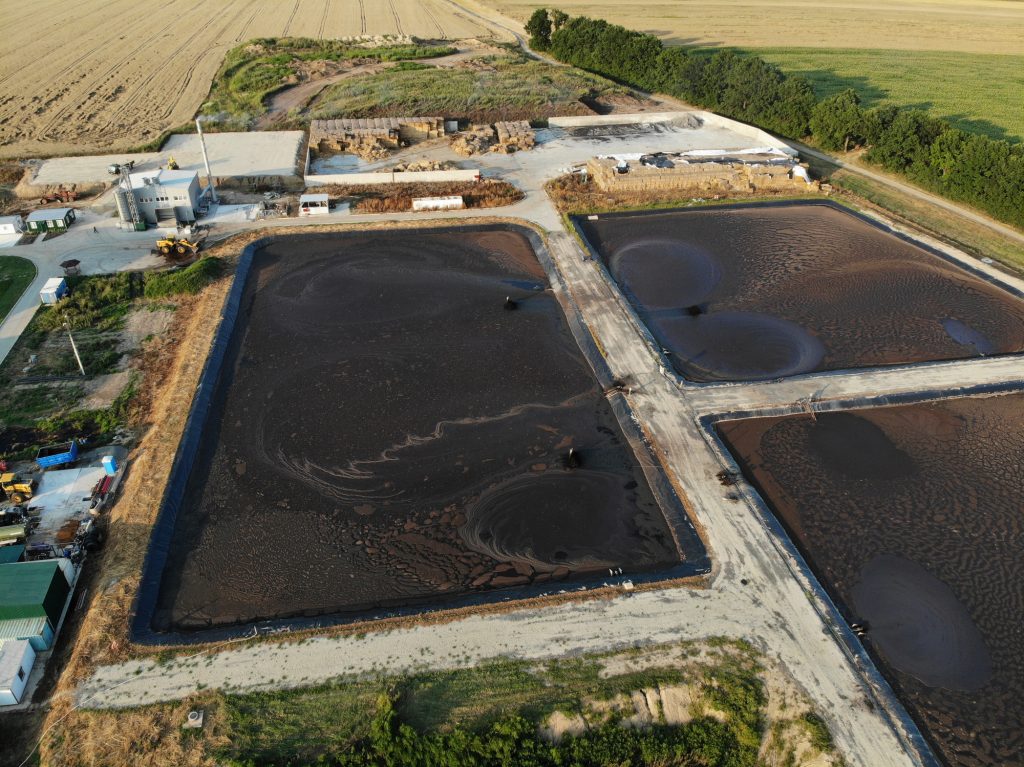
At the site in question, we faced a tough challenge: hundreds of thousands of tons of chemical waste and millions of gallons of contaminated water. This material was spread out for miles in various pools on the remediation site. Having such a diffuse feedstock is much more difficult for processing than having a single starting point, like discharging a rail car. Further, the material was extremely problematic: a non-uniform mixture of volatile organic compounds, semi-volatile organic compounds, polychlorinated biphenyls, and metals.
How does one begin to drain this sea of chemical sludge? First, we tested the material to see just what we’re dealing with. After performing some basic trials at our facility, we determined a complete materials test and flow report was necessary. Fortunately, Solids Handling Technologies was willing to play with fire and test this hazardous sludge. They performed cohesive property and wall friction tests to determine which opening sizes best promote material flow. Rather than relying on rules of thumb, we were able to confidently design the equipment based on the specific properties of the material in question.
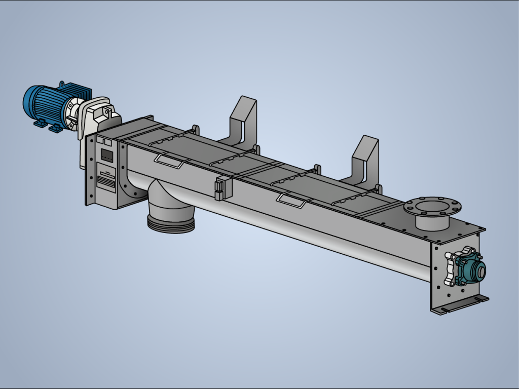
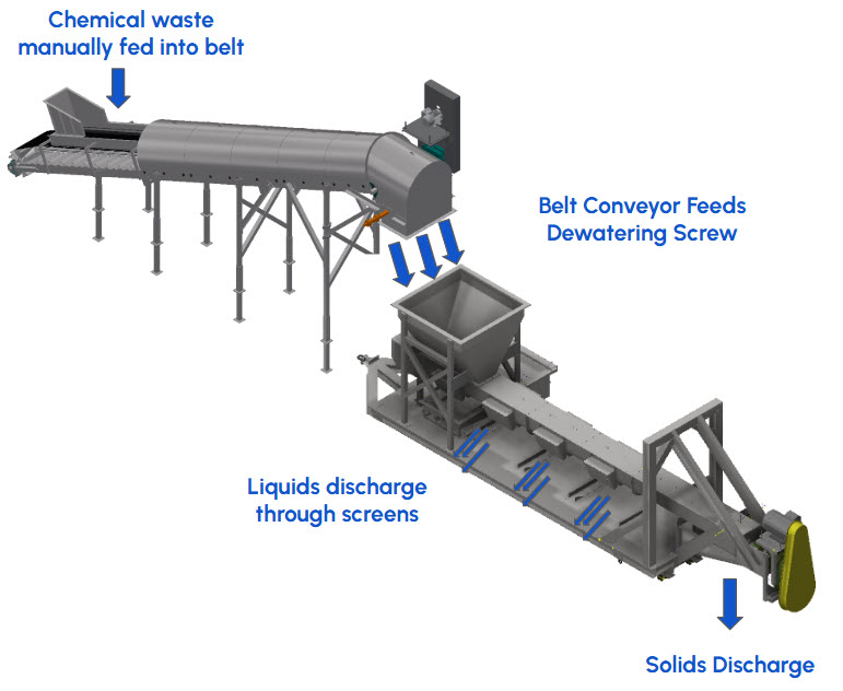
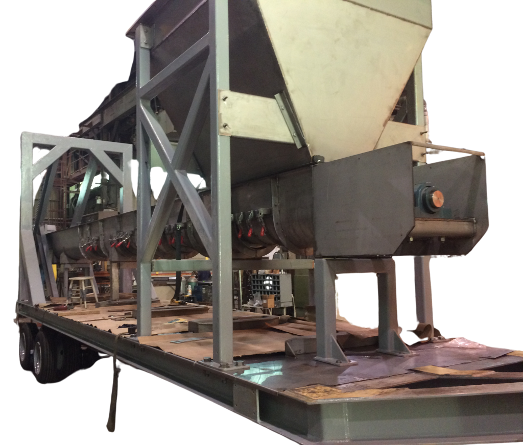
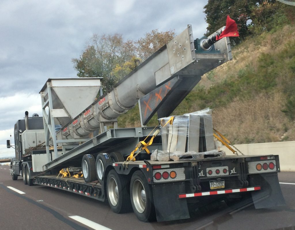
Informed by the test results and leaning on our experience, we devised (2) integrated conveyors: a 30” incline belt conveyor feeding an 18” Ø screw conveyor with four large screens. Both units were fabricated on a trailer to be towed between various site locations, thus solving the issue of diffuse feedstock. The screens allowed liquid discharge while the screw carried the solids out to the final outlet. Separating these distinct components is key to streamlining future processing.
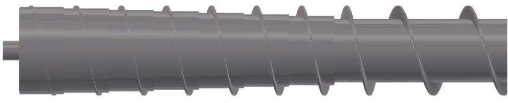
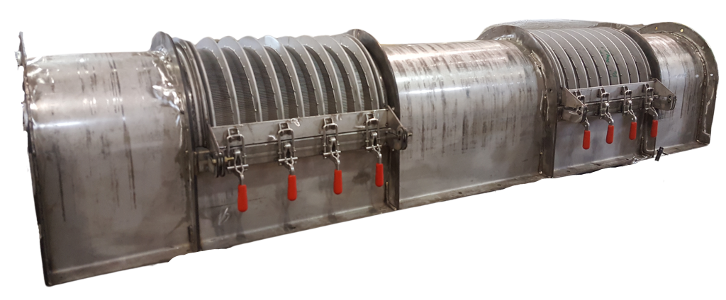
This screw feeder features a very unique design. There are (8) different diameters of pipe stacked in descending order. This mimics the effect of a mass flow screw conveyor by increasing the available volume for the material to fill. This solution offers better material flow while saving on the fabrication and design costs of a true mass flow screw feeder. Also, after the inlet portion of the screw, the flights increase pitch. The purpose of modifying the screw pitch in this manner is to provide greater volume to relieve the material.
Given the adhesive and agglomerating tendencies of the material, no internal supports could be used. An internal hanger bearing would have caused a maintenance nightmare, and perhaps clogged up the U-Trough. We sized up the pipe from a standard 4” diameter to 12” diameter. This may seem extreme, but the screw needs to span 30 feet and is under heavy load. Due to torque requirements the shaft diameter was also increased by a factor of 2.5.
This project was an extraordinary success. We have continued supporting both general maintenance and design improvements on this system, and have built a duplicate unit for another one of the customers’ sites. Thomas & Muller is proud to contribute to the ongoing efforts to clean up the legacy of American industry.